
Garage ceiling lighting
About
This page is of interest if you want to understand the basics of different light sources/fixtures and how to use them to illuminate a garage/workshop. If you jump to the bottom you will find some examples.
Note for my swedish audience: words that are underlined have a hover function. Place your mouse over the word and you can see the swedish translation.
Background
|
I have just built an 8.5×5.3 m garage/workshop with 2.6 m ceiling height in Sweden (northern
Europe). Current status is that it's completed on the outside but the inside is not even insulated.
Before completing the interior I want to decide what the ceiling light should look like. The simplest way
would have been to just mount a bunch of cheap raised fixtures with T8 fluorescent tubes but my curious personality made me dig into the
subject a bit. I'm an engineer but without any expertise in lighting nor electrical installation. So have this in mind when reading this page (which you of course always should when reading stuff on the Internet). Please also note that the facts on non-LED light sources are quite uncertain, I got most of the information from manufacturers datasheets but I did it quickly. I have deliberately left out most source references and detailed arguments for 2 reasons; 1) It would take me more time to write this page, 2) This page would take people much longer to read. |
|

Prerequisites - Technical basics to understand
Lumen, Lux and Candela
You should understand the concept of Luminous flux (Lumen), Illuminance (Lux) and Luminous intensity (Candela) before going on. You can read more on them at Wikipedia (Lumen, Lux, Candela). Basically what you need to understand in the context of this web page is that;
- Lux defines how much light we humans perceives hits a surface.
- Lumen is the total amount of visible light that is emitted by a light source/fixture. Lumen=Lux×area.
- Candela is the amount of visible light that is emitted by a light source/fixture in a particular direction.
Total Lumens needed
It seems as you should have at least 500 lux in a garage/workshops working area (the car hood or a table for example) if you intend to do some serious work there (see for example Illuminance - Recommended Light Levels).
The total emitted light from the light source/fixture is calculated as Lux×area. My garage for example will require 500×8.3×4.9=20300 lumens. Note that this value isn't exactly the same as the total luminous output from all light sources/fixtures in the room. As described below (under heading "Illuminance calculations"), the light that hits a surface from an angle is perceived as weaker. So the total luminosity we need from our light sources/fixtures are typically greater than this value. How much greater you wonder? This is best simulated but if the light fixture is good (doesn't spill much light at wide angles) and you place them well, an overhead of 20% should be fine (for narrow beam spotlights this can be reduced to less than 10%). In my example this means that my light fixtures should produce about 24,000 lumens.
Light distribution
|
By light distribution I mean how the light is spread across the room. Having a single spotlight in the middle of a garage will quite obvious be a bad solution. But how many spotlights would be needed to get an even light across the room? I will explain this below. But first I also want to mention that having too few light fixtures will cause uneven light and annoying shadows.
Different light sources/fixtures spread their light in different ways. The datasheets for light
sources/fixtures often have a "beam angle" defined. A spotlight can typically have a beam angle of
40° while a tube light fixture typically have 120°. Within the beam angle, the illuminance is
at least 50% of the illuminance directly underneath the light source/fixture. Illuminance calculations
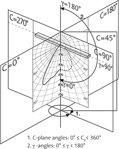
The illuminance at a point directly underneath the light source/fixture depends on 2 things; the
luminous intensity from the light source/fixture (which is given by the value at angle 0° in the
luminous intensity distribution polar graph) and the height from the light source/fixture to the point
of interest.
The illuminance at a point away from the light source/fixture is most often defined as the "horizontal
illumination". The horizontal illumination is the illumination you get on objects that are placed
horizontally, like the floor or a table for example. The wall and a front windshield of a car for
example, are not horizontal. The horizontal illuminance at a point away from the light source/fixture
depends on 3 things; the luminous intensity from the light source/fixture (which is given by the value
at angle 0° in the luminous intensity distribution polar graph), the height between the light
source/fixture to the point of interest and the angle between the light source/fixture and the point of
interest. There are free software tools that can help you to simulate the illumination. I have tried 2 of them briefly (DIALux and Relux) and my conclusion is that they work but it takes some time to learn how to use them. And the light source/fixture data must be available from the manufacturer in a correct format. Guiding rules for placement of light fixturesTo simplify the illuminance calculations above we can state a few guiding rules. h in the formulas below is the height between the light fixture and the lit area of interest (in our case, typically the vertical distance between the inner roof and the table/car hood).
The above list is only valid for light sources/fixtures that emit light evenly in all directions onto
a surface. This covers most light sources/fixtures but not tube lights and LED strips. Tube lights and
LED strips can be considered as an array of small light sources. Each of the light sources in the array
will behave as an ordinary light source. So tube lights and LED strips can be placed according to the
list above in one direction but in the other direction (end-to-end) it gets a bit more complicated. |
|
||
|
|||
Examples of different light sources/fixturesIn the graphs to the right you can see real world examples of the light distribution from 3 different light sources/fixtures. It can be seen that the example fluorescent tube fixture provides a very even light within 90°. The LED spot shows the characteristic beam. The example LED tube shows that about 15% of the light is emitted outside of 120°. The reason for this "waste of light" is most likely the diffuse plastic cover around the tube. A fixture with a good reflector is needed to direct this light more downwards. |
|


Light quality
"Light quality" can be measured in several ways but the most used term is currently CRI. CRI tells how well a light source reveals the color of illuminated objects. A CRI value of 100 is considered perfect and is what you get from the sun and an incandescent light bulb. A high CRI alone isn't enough to determine if the light is of "high quality" but it's a good start. LED manufacturers are now also talking about the R9 and R13 values, the GAI value and CQS.
The Correlated Color Temperature (CCT), which is a measurement that indicates if the light is perceived as cold
or warm white, is another perspective when talking about light. It doesn't effect the "Light quality" but it
effects how we perceive the light. For some installations you want a high CCT value (a workshop for example)
but for some you want a lower value (the bedside lamp for example).
I think that a color temperature of about 4000 K is good for garage lighting.
To sum it up; "light quality" isn't that easy to get a fixed number for. And also, how good quality do you need in you installation? Usually you have to make a trade-off between "light quality" and energy efficiency.
Efficiency
Luminous efficiency (or efficacy), lumen/watt, is the ratio between the emitted light and the electrical input
power. The maximum lumen/watt that can be obtained is 683 lumens/watt but this number can only be achieved using
green light (at 555 nm). For very high quality white light the maximum lumen/watt is about 250. This is the
figure we use in the remainder of this page to define luminous efficiency.
All light sources that require an electric power different from the source power needs a driver
(voltage/current converter). The power losses in the driver must of course also be part of the efficiency
calculation.
LED lifetime
I think a note on LED lifetime is in its place. When manufacturers specify the lifetime they generally specify
it as being the time it takes for the LED to loose 30% of it's luminance. This lifetime specification requires
that the LED is operated below a specified temperature and below a specified current. There's a rule-of-thumb
in electronics; every 10 °C increase in temperature halves the lifetime. But the Achilles' heel is the
driver! The driver consists of many small components and each of these have a limited lifetime (some follows a
rule-of-thumb in electronics; every 10 °C increase in temperature halves the lifetime). If the driver will
malfunction before the LED is a matter of how well the driver is designed and how well the LED and driver are
cooled.
So to sum it up; if the driver is designed for a long lifetime at the used operating temperature and is
designed to keep the output current below the LEDs specified current rating it's a good driver. And if the LED
is mounted in a way that assures it's operating below its specified temperature it's a good LED design. The
final thing to look at is if the end user (you) is installing the LED and driver in such a way that they get
enough cooling.
Light source types
There are quite a few types of light sources as can be seen in this List of light sources. I will only mention a few of them (since I already knew that I was going to use fluorescent tubes or LEDs).
-
Conventional 230 V incandescent light bulb.
This traditional light source is cheap, simple and has good light quality but poor lifetime and efficiency.Efficiency: ~5% for a 100 W bulb. CRI: 100. Lifetime: ~1,000 hours. Price: Low. Temperature sensitivity: TBD. -
Compact fluorescent lamp (CFL).
This low energy alternative to the conventional incandescent light bulb has a good efficiency and lifetime but are more expensive and has poorer light quality. They also contains mercury which is a drawback if the light source isn't recycled.Efficiency: 15-35%. CRI: 80-90. Lifetime: 8,000-30,000 hours. Price: Medium (the cheap shit excluded). Temperature sensitivity: TBD. -
Fluorescent tube (T8 & T5).
The tube light source has a large light emitting area, good efficiency and lifetime but are more expensive and has poorer light quality compared to the conventional incandescent light bulb. They also contains mercury which is a drawback if the light source isn't recycled.Efficiency: 33-38%. T5 tubes has about 10% higher efficiency than T8 tubes. The fixture can however be made more efficient for T5 tubes so the overall efficiency can be increased further by 10-20%. CRI: 80-100. Lifetime: 10,000-50,000 hours. Price: Medium (the cheap shit excluded). Temperature sensitivity: T5 tube only emits 45% of the nominal light at 10 °C. T8 tubes emits 80% of the nominal light at 10 °C. This can be improved by mounting the tubes in a ceiled housing and/or using "HO" tubes since they will then self heat. - LED.
A LED light source comes in many different variants; incandescent light bulb replacement, halogen light source replacement, fluorescent tube replacement and LED strip are the variants I have considered. I will cover these variants in more detail further down on the page.
You must understand the difference between a LED and a LED. There are not so many companies that produce LEDs used for lighting. But still there are thousands of manufacturers of LED light sources, in very different price ranges. One reason for the difference in price is called "binning". Binning means that the LED producer measures the performance of each LED and groups them together. The good ones are used by the serious companies and the bad ones are used by others. The LEDs are sensitive to too high temperature and this is something that serious companies take care of. Others don't care about it so much which will cause your LED light source to loose light and burn up prematurely. A good LED design will last tens of thousands of hours while a poor LED design can start deteriorate immediately.
After some web searching it's also noticeable that manufacturers lie a lot! Some specs are simply impossible to reach and definitely at the extremely low price tag that some of them have.Efficiency: 25-50%. CRI: 80-90. Lifetime: 20,000-100,000 hours. Price: High (the cheap shit excluded). Temperature sensitivity: Low temperatures extends lifetime of the LED and the driver. A quality driver will operate down to at least -20 °C.
How many and how powerful light sources/fixtures do you need?
First decide how many lux you want. Then choose light source type. Then calculate how many light sources/fixtures you need to get an evenly distributed light. Then calculate how much lumen you will need from each light source. If things doesn't add up, try the steps above but change some parameter. Look at the examples below.
Examples
MR16/GU10 type light fixtures
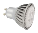
By "MR16/GU10 type" light fixtures I mean small recessed housings with a directional light source. The most common form factor is the MR16 and it's GU10 derivative. The light source can be halogen, LED or fluorescent. The GU10 is run from mains voltage (120/230 VAC) while the MR16 also can be specified to be powered from a lower voltage (12 VDC). It seems as MR16/GU10 halogen light sources rated at 50 W produces somewhere between 300 and 800 lumens. Halogen light sources has the disadvantage that their lifetime is quite poor, at least when running at full power and from a mains voltage. MR16/GU10 with LED as light source consumes much less power and has a longer lifetime. However, to get a luminous equivalent for the 50 W halogen we must look at for example OSRAM's MR16 rated at 620 lumen. It consumes 12 W (which seems like a bit much, I'm sure there are better alternatives out there). A rough cost estimation for using halogen GU10 with fixtures in my garage is 39×($4+$6)=$390. A rough cost estimation for using LED MR16 with fixtures and AC/DC converter in my garage is 39×($30+$6)+$75=$1480. |
|

Large downlight light fixtures
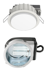
Large downlight light fixtures have 2 main advantages over MR16/GU10 lamps; they have a larger light emitting area which gives them a better light distribution and they can deliver more light. The light source can be of several types but CFL and LED seems to be the most common. As an example of a Large downlight LED light source/fixture one can mention OSRAM's 180 mm LEDVANCE XL WT which gives 2000 lumens while consuming 19 W. A rough cost estimation for using large downlight LED light sources/fixtures in my garage is 15×$160=$2400. Another alternative is to buy used large downlight CFL sources/fixtures for around $20 each. |
|

LED panels
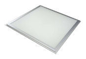
The LED panel is more or less the same as the Large downlight LED light fixture. The main difference is that they are larger, normally 60×60 cm or 120×30 cm. |
Fluorescent tubes
|
The fluorescent tube (T5 or T8) is quite
cheap, cost is about $5 for a high
quality tube. The price for the fixture is more
difficult to say. There are very cheap fixtures. For T8 tubes, the cheapest fixtures has a magnetic ballast and a starter that causes flickering light and consumes about 20%
additional energy. The electrical ballast, which
is required for T5 tubes, is much better since it consumes less energy, turns on the light faster and
in some cases allows dimming. The downside is that it adds cost to the fixture. After doing a quick web
search it seems as you can get the cheapest 1.2 meter fixtures for about $30 while the ones with better quality/efficiency costs at least
twice as much. Another option is of course to buy used fixtures.
The luminous output from a tube varies with make and model but a quick look at OSRAM indicates that a
standard 1.2 meter T8 tube delivers 3,300 lumens and that a High Output T5 tube delivers 4,300
lumens. The lumen output figures from the
fluorescent tube manufacturers is only valid when using a "ballast factor" of 1. The "ballast
factor" defines how much power the ballast will supply to the
fluorescent tube. The luminous output
from the fluorescent tube will be the
fluorescent tubes specified luminous
output × the ballast factor. The ballast factor is normally around 0.9 but can be in the range
0.7-1.2. One must not forget that the luminous output of fluorescent tubes are sensitive to temperature. If they are to be used in a garage with none, or very little heating, the fixture should be of a sealed type. Perhaps one should also use "High Output" tubes.
I want recessed fixtures since
I think it's stupid and ugly to have the fixtures hanging down in the room. But this showed to be a bit
problematic since I wanted to mount them in a certain direction. A rough cost estimation for using fluorescent tubes with the cheapest fixtures in my garage is 8×($5+$5+$30)=$320. A rough cost estimation for using fluorescent tubes with simple but high performance fixtures in my garage is 8×($5+$60)=$520. |
|

LED tubes
|
A LED tube is meant to be a direct replacement of a fluorescent tubes. There is however one major
difference; the fluorescent tube is
omnidirectional in its light
distribution. All LED tubes I have seen have a beam angle at around 120-160°. So in most cases,
there is little need for a light fixture that directs the light downwards. Most LED tubes comes in T8 form factor. The reason is probably because most installed fluorescent tubes are of T8 type and because the T5 tubes are good enough to keep.
As of now (Q1, 2015) most high performance T8 120 cm (4') LED tubes have a lumen output of 2000-2500
lumen. This can be compared with a standard T8
fluorescent tube which has a lumen output of 3000-3500 lumen. The LED tube will in most cases
loose less of it's output in the fixture so the real difference is not so big. To get the highest efficiency, one should remove all electronics and everything in the fixture that is in the way of the light (lens and louvers).
|
|
|||||||||||||||||||||||||||||||||
|
||||||||||||||||||||||||||||||||||

LED strips
|
Important note regarding LEDs; the cheaper ones are cheap for a reason. I strongly recommend that you use the ones that are made by serious companies. In theory the LED strip is easy to install (just use the self adhesive tape to attach them to the ceiling) and very cheap (from a few dollar per meter). First we need to figure out how powerful the LED strip must be. In my garage I would want them to run along the long section of the ceiling, hence be about 7.5-8 meters long. I think that 2, 3 or 4 of them would be good for the light distribution. Currently, LED strips produce about 80-100 lumens/watt.
Using LED strips that are rated above 10-15 W/m will in most cases require them to have extra cooling. At least cheap LED strips don't have enough heat spreading material so they will deteriorate (burn up) very quickly. A way to solve this is to mount them on an aluminium profile but these are quite expensive and they require that the adhesive on the back of the LED strip is of very good quality (very cheap LED strips most certainly do not use 3M adhesive, even if it says so). Most of the LED strips use series resistors to regulate the current. This is very simple and cheap but means that it's impossible to achieve high efficiency while keeping the luminous output constant over source voltage variations, LED tolerances and temperature variations. LEDs with no active regulation also suffer from "thermal run-away" (they get hotter and therefore consume more current and therefore get even hotter...). Active current regulation is much better since it can provide a more even luminosity at a high efficiency. The active current regulation can also protect the LEDs from overheating since it can be designed to reduce the current if the temperature rises. The power conversion efficiency for most LED strips, with series resistor or active current regulation, will be about 75%. 15% is lost in the LED strip current regulation and 10% is lost in the AC/DC voltage converter. One more thing to consider is the surface protection. I want some sort of mechnical protection for the
LED strip and this can be achieved in 2 ways; using an aluminium profile that also contains a plastic
cover or use a LED strip with some sort of transparent coating. Both of these solutions costs money. The
transparent coating also has a potential problem, if the coating is made of an inappropriate material,
it can become less transparent when aging. The coating will also have a negative impact on the
cooling and luminous efficiency (at least 5-10% loss of luminosity). An important note when using the LED strip in a non-heated garage is that the temperature variations will stress the self adhesive tape on the back. This will cause the strip to eventually fall of the ceiling. OSRAM recommends that their LED strip is cut every meter to reduce the stress in installations with varying temperature. LED strips generally have the same light distribution as LED tubes so look there for a more detailed description on how to space them to get an even light. The only LED strips that I found usable (OSRAM, Barthelme, Solarox, Flexfire LEDs, Solid Apollo LED, Diode LED and LED World for example) were quite expensive. A very rough cost estimation for using LED strips in my garage is $1000. |
|
